
Hydro Power 13
If this project was going to get off the ground in a serious way, I needed more water to be delivered down off the hill.
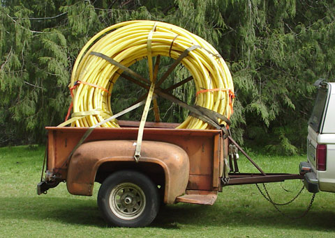
One day while cruising through an auto wrecking yard down in Reedsport, I spotted a big stack of 1¼" yellow polyethylene pipe. There were about twenty coils of the stuff, each 500 feet in length, still secured (mostly) by the original strapping. I inquired about this, and negotiated to purchase four coils (2,000 feet) for a reasonable price. I would have to come back with my trailer to pick it up, which I did a day or two later.
The yard monkeys who brought the pipe out of the yard did so by arriving with all four coils held up by a forklift. I was pretty sure that I wasn't going to be able to lay the pipe down, so I told them to stand it up in the trailer bed. After I got a couple of ratchet straps on the pipe, they let the forks down and beat it back into the yard.
The pipe wasn't very cooperative, and two straps barely kept it from falling over, so I ended up spending quite a bit of time trying to manage the bundle while putting on the remaining straps. Eventually, I had it secured well enough that I thought I could get underway. After a few miles, I stopped alongside the road and checked the load, it seemed to be holding.
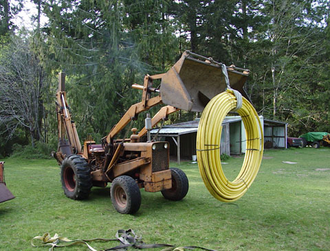
At home, I used my backhoe to lift the whole stack off the trailer and laid it on the ground. One by one, I picked up the coils, moving them to an area behind my storage locker for eventual installation up to the water source on the hill.
Having secured the penstock, I happened to be at the recycle yard in town one day and came across some commercial dishwashing equipment, something that had been removed from the casino, I think. There were three motors in the equipment, each three-phase, 240/460 volt. Two of the motors were 2 horsepower, while one was ¼ hp. All of them had stainless steel shafts, which is never a bad thing when working with water-driven systems. These would make usable generators for my upgraded hydro project, so I removed and purchased them. The 2 hp motors cost me $6 each, while the smaller motor was $3.
I put the larger motors into storage, they were very dirty, and had noisy bearings, but they were rebuildable. The smaller motor, I intended on experimenting with sooner. I purchased an arbor that would fit the motor output shaft and allow me to attach the new turgo runner.
I had to do some quick self-education, as induction motors are a bit different from using a permenant magnet DC generator. In order to make an induction motor operate as a generator, it's necessary to cause self-excitiation by placing capacitors in the correct configuration and values across the field windings. I scratched around and found some old caps in air conditioning units at the yard and cobbled together a test of the motor-as-generator.
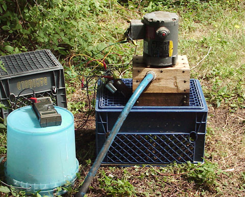
Because I has very little water to work with, I found I had to set up the field windings of the motor for 460 volt operation to get it to put out approximately 200 volts AC. The value of the capacitance seemed to make a lot of difference to the voltage, and also to the speed of the runner. I tried various configurations of the field windings, Wye and Delta at each voltage, as well as connecting incandescent lamps as loads. Changing the nozzle diameter changed things too, the power the plant put out and the net head pressure on the water line. What I found was that the plant operated best with the smallest nozzle.
This was all a lot to process mentally, and I needed to go "back to the books" to help me understand. I had also downloaded some spreadsheets that allowed calculations to be run taking into account net head pressure, runner diameter and number of spoons, nozzle diameter, motor efficiency, etc. This was becoming a very complex lesson.
One thing that was obvious right from the first was that with so many electrical connections, and so many possible configurations of wiring, that clip leads wren't going to cut it. Aside from the fact that I didn't have a whole trunk full of leads, they tend to fall off, have exposed ends that can cause shorts, and when you have a big tangle of them, trying to keep straight which lead was connected where and to what becomes a brain buster. What I needed was a test board...
...So I built one, literally on a board.
Each of the windings in the motor were brought out individually to a long-ish cable with a multi-conductor plug and socket which was terminated on a terminal strip. Wires with push-on connectors and labeled with adhesive numbers allowed me to easily and quickly identify windings. All of my hand-drawn diagrams had the same numbering system. Three 10μf capacitors with quick connect terminals were mounted, as were three medium-base edison sockets for incandescent lamps. There were a couple of "unassigned" terminal strips that could be used to connect quick-connect leads together, allowing me to make series or parallel connections.
Because several operating conditions can cause an induction motor to lose its residual magnetism (short circuits, running down with a load connected, sudden overload, etc), it is necessary often to "flash" the windings with a small battery. I installed a small knife switch that would allow me to disconnect one winding and momentarily connect it to a 9 volt battery to do the job with the push of a button.
This test rig would make experimenting with the induction motors much easier, as many of the needed connections could be made on the board quickly with the quick-connect wires, and for the most part, there was some order to the wiring, as many of the connections had an established place on the board.
Because capacitance plays such a significant role in making an induction mtor run as a generator, and the value of the capacitance needs to be varied to "tune" the output, I needed a lot of capacitors on hand. These aren't the fifty-cent small components from radio shack, but $5 - $7 and up components. Fortunately, I ran into a large number of high-intensity discharge light fixtures that had been scrapped. Each contained a 15 microfarad, 440 volt AC capacitor with quick-connect terminals and a bleeder resistor attached. In exchange for separating the various components (cast aluminum, steel, copper wire, etc), the recycle yard operator allowed me to keep the capacitors, which had little scrap value. Now I had 24 capacitors that could be connected in series or parallel combinations to create nearly any value that I needed.
A few minutes with a cable cutter brought me the wiring guts from a couple of commercial air conditioning units. With this I made a big batch of test leads with quick-connect terminals on each end to allow me to make connections between the various capacitors, windings, loads, etc. In all, I was slowly building an entire hydro laboratory.
The results of continued experimentation with the ¼ hp motor showed that when optimized, I could make not quite the same amount of power as the DC permanent magnet motor when running up at the house. It was time to go down to the lower garden where the line pressure is greater and try again.
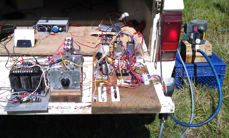
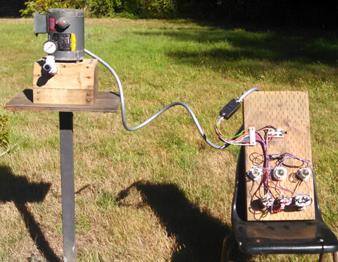
Hence, the tailgate lab setup.
More water pressure meant more power. It also meant that I needed a different value of capacitance. In the image, I'm using a 3 phase variac transformer to allow me to add or subtract an additional bank of capacitors to 'tune' the output of the generator. I'm running the resulting 240 volts AC through a 3Φ transformer and rectifier. The resulting direct current is charging a 24 volt battery in the bed of the truck. Pity that the analog meter face is washed out, I'd like to remember what the total amount of power was...
Original material ©1996-2026 Mr. Sharkey | All rights reserved