
Load Control 3
Now that I had a method of reading the data coming off of the mouse, I needed a way to get this info off the Arduino board and out into the real world to do some work. One of the motion control web pages I found while researching was a description of an interface to control a simple remote control car by using mouse movements. The RC car was a very elementary design, with simple push buttons for forward, back, etc. The provided sketch of the code looked like it could be used to illuminate LED lamps when the mouse was moved, so I tried it out, using red and green LEDs for movements forward and back (Y-axis) on the mouse. This worked fine, and it also meant that I now had a way to see what the processor was doing with the mouse movements without having to have a USB cable connected to a computer and a terminal session open and running.
The two LEDs would blink, or pulse briefly, each in turn, depending on the direction the mouse moved. The pulses would be few and far apart when the mouse was moved very slowly, and would speed up as the mouse moved more quickly. This was great! Best of all, when the mouse was stationary, neither of the LEDs would illuminate. ~Exactly~ the behavior that I wanted for the Variac controller!!!
It didn't take more than a few clock cycles inside my head to figure out that the pulses put out by the Arduino were almost exactly like those my 555 timer board was making. Since the Variac already had optoisolated inputs, it was a simple matter to connect the wiring from the old 555 board directly in parallel with the two LEDs and try the new system out. Using the mouse on a surface would turn the Variac up and down reliably, and the variable rate of the pulses worked very well to "hurry up" the Variac when the mouse was moved quickly. In fact the pulses were so close together when the mouse was accelerated that the Variac drive motor ran as though it had been simply switched on! I was beginning to get a very good feeling about this!
Originally, I had thought that I'd need a different drive system for the Variac, a stepper motor, or a large servo motor, something with more muscle. This would complicate the project, as I don't have very sophisticated machining abilities or tools. As it turned out, the existing motor drive in the Variac was responding very favorably to the control signals from the Arduino. I decided to run with it and see how it turned out. Couldn't be a whole lot more kludged together than what I'd been using.
The last task was to see if the optical mouse could read the rotating disc inside the electric meter. Since balancing the whole mouse on top of the exposed disc was not going to work, I shredded up the mouse case, removing the small circuit board inside and leaving behind the buttons, wheel, etc. Applying a couple of tabs of cellophane tape to the bottom of the circuit board held the clear plastic lens assembly in the proper position, as it was needed to focus the light and image for the optical sensor on the board.
I threw together a couple of thin aluminum strips, screwed them to the face of the meter where the old "cyclometer" dials had once been and secured the circuit board with a couple of binder clips. This allowed me to adjust the position and distance of the mouse optics in relation to the disc.
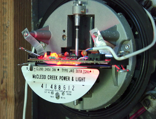
(McCleod Creek P&L is my own moniker for my personal PV and Hydro generation
facilities here at home, it has nothing to do with any "real" utility company)
This actually worked!! Amazing!!!! The mouse was able to sense the disc rotation, and since I had already proofed the concept and connected the Arduino board to the Variac, the system was now fully operational. Just like that! I was astounded!
Turning the circuitry loose in a production environment produced no disappointments. When solar generation exceeded the household loads, the disc would try to spin to the left, but the Arduino would turn the Variac up, quickly at first if the load change was sudden and large (refrigerator turning off), then slowly drop to only a few pulses, then a single pulse every second or so until the disc in the meter movement was nearly stationary. Loads turning on produced the opposite reaction, the Variac was turned down until power parity was reached, then the system went idle until the next change was needed. I had achieved the exact results I had wanted for so long, a fast reacting, but ultimately sensitive dump load controller.
At the end of the day, when the sun got weak and insufficient PV power was being produced, the controller turned the Variac down until the limit switch turned the transformer off, putting the system to bed until the next morning. The disc continued to rotate to the right, the red LED pulsing, but no action being taken, as the system was "asleep".
Not only did it look like this was going to work, it was already working very well, and I hadn't even begun to refine the system.
Original material ©1996-2026 Mr. Sharkey | All rights reserved