
Load Control 4
Although the controller seemed to be working well, I did notice that there was some "creep" in the disc that wasn't being detected by the optical mouse. When the power level running through the meter was very small, the disc would turn very slowly and the mouse would "wake up", turning it's internal LED on to full brightness, but the controller would not indicate that there was any movement, and the Variac would not be adjusted. Checking the data coming off the mouse using a terminal session showed that in spite of being awake due to the motion, it wasn't putting out any motion coordinates. Nothing for the Arduino to work with.
Assuming that perhaps the smooth aluminum disc inside the meter was too shiny or featureless to stimulate an output from the mouse, I covered the rim of it with painter's masking tape, postulating that the crepe texture of the tape would make the mouse more sensitive to movement. This did increase the sensitivity, but not enough to keep the important feedback loop to the Arduino informed of any and all disc movements.
Time for more research. I read up on optical mice, learning that they are essentially small cameras with embedded memory and processing that compares the past and present images in the lens, and then uses this to create the data corresponding to movement. Like other optical devices, mice have a resolution specification, expressed in d.p.i. (dots-per-inch), and sometimes c.p.i (?-per-inch). Low budget mice were nearly all of the 400 dpi sort, but graphics designers and gamers who needed more sensitivity usually purchased higher-end mice, ones with 800, 1000, or even 2,000 dpi. Laser mice are capable of a staggering 5,700 dpi. It was beginning to look like my made-in-china junk box mouse wasn't going to cut it. I cruised through some auction sites and found laser mice for not too much money, maybe I'd have to bite and buy one of those...
Before succumbing to purchase impulse, I dug a little deeper into my junk box and found a "fancy" A-Open mouse that I had gotten some years earlier with the expectation that it's four buttons and two wheels would make navigation in my recording studio software easier. It didn't and the numerous buttons and bulky running-shoe shape of the mouse left me cold, so I pitched it.
However - a quick search online showed that it was an 800 dpi optical system. Could this improve my disc-reading abilities?
As before, a phillips screwdriver stripped the rodent bare, and I only had to make some adjustments to the temporary aluminum mounts on the meter to put it into place.
The increased resolution was more than enough to solve the issue at hand even without the coating of tape on the disc. The disc in the meter was now incapable of making any motion at all without sending the Arduino into immediate action. Even opening and shutting the garage door next to the meter set up enough vibration to send the Variac skittering to compensate for the disturbance.
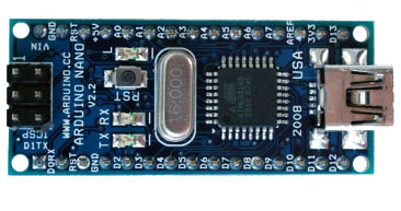
It was now time to begin making plans to assemble this prototype into a permanent enclosure. Since I had gutted the electric meter, I reasoned that building it all inside the glass dome that used to house a collection of gears and dials would be fitting. But would it all fit? The Arduino could squeeze into the area above the disc, taking up only a small amount of depth, but with close tolerances to the top and sides. Then I remembered that this was the Duemilinove, and that smaller boards were available. Got online and ordered up a Nano, that would take up less space.
The other concern was what I was going to do with the mouse guts. The optical chipset itself wasn't very big, but the circuit board it was mounted on took up a lot of space. I didn't need the five microswitches for the buttons, nor did I need the two optical encoders for the wheels. Hmm, some circuit tracing here and there, maybe I could hacksaw off parts of the board that I didn't need, sloppy, but more compact.
On an impulse (I get those a lot), I searched up the component designation on the optical chipset. One of the first results was a complete datasheet for that very IC, and I didn't have to wade through a bunch of "datasheet-online" scrum, it was posted right on the manufacturers web site! Most helpful of all was the "typical PS2 application" schematic diagram contained in the PDF file:
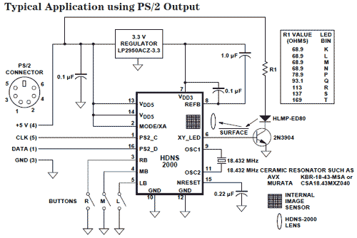
Since the circuit board used all through-the-hole components, it would be simple matter, using this schematic, to desolder the components and mount them on a compact, custom perforated project board. Everything I'd need is already mounted on the mouse circuit board, the capacitors, the resonator, everything. This would allow me more freedom in placing the optical sensor inside the meter, perphaps reading the edge of the disc instead of the flat face (still have to test that).
To get DC power for the Arduino and the mouse, I tore open an old 5VDC, 1A switching power supply from an IOmega zip drive. Very compact, very efficient, and it can run from 240 VAC, already available inside the utility watthour meter. It might just be time to begin building this project....
...or not....
Original material ©1996-2026 Mr. Sharkey | All rights reserved