
Solar Power Diversion Load Controller
Short days and long nights create the need for indoor projects, at least for me so I don't surf the same websites, hitting "refresh" over and over in the hopes that some new content will be posted. Here's the start of a "build thread" concerning an electronic project to squeeze the last watt-hour of electricity out of my PV array and deliver it to me in a usable form.
Since on an instantaneous basis, my 1,300 watt photovoltaic array can produce more power than I may be able to consume, and the system batteries are kept in a state of constant float charge, any power produced in excess of what my household appliances consume is essentially wasted. What is needed is a method of detecting this excess power production, and shunting it to a useful purpose, in my case, heating water in my domestic water heater tank.
Because the amount of power produced varies with weather conditions, time of day, time of season, and because the loads imposed by my home and appliances also varies, it's not possible to use a "set-it-and-forget-it" load on the system. In order to effectively administer the power, it's necessary to sense the loads and apply a proportional amount of power to the "dump load" (water heater), even if at any given moment, that might be zero power due to low production or high consumption.
This is not a new concept for me, I've been using a system of this description to capture excess PV production for over four years. At the time I built the original dump load controller, I had access to only rudimentary materials and tools, but I pressed ahead and built an electromechanical nightmare that did the job, perhaps not as efficiently as it could have , but it worked.
What I built involved a standard, rotating-disc, utility-type watthour meter, the type you see on the sides of buildings everywhere. This particular meter was mounted in my garage, and it was on "my side" of the regular utility meter that the power company reads to determine my monthly consumption. On the bottom of the rotating disc, I placed two strips of black plastic electrical tape, then mounted two optical sensors such that only one of the sensors was looking at black tape at any one time (this involved restricting the disc to being able to rotate only a few degrees in either direction). The signals from the sensors were fed into a Rube-Goldberg contraption of 555 timers to decode and create control signals to the dump load. There was a 555 clock chip, two Schmidtt triggers, and two one-shot timers, all synchronized and interlocked to detect which direction the rotating disc was turned and provide control pulses as an output.
Here's the prototyping breadboard of the circuit. It never got much beyond this stage. In the rear is the panel from the watthour meter with the two optical sensors installed:
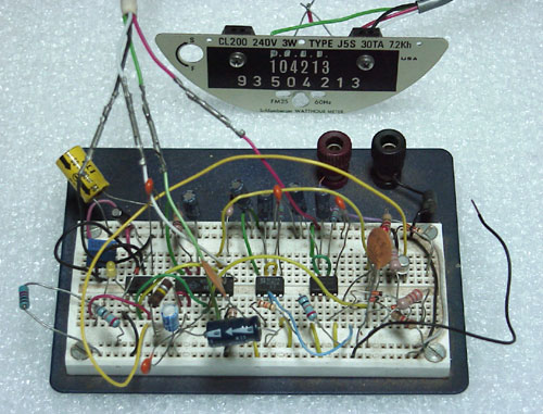
This tangle of components hung out on a scrap of mahogany wedged between my load center and second electric meter for all those years, gathering dust while operating. It's amazing that it never got knocked off or the wiring scrambled by being disturbed while I worked on all other manner of other things in the garage.
For the most part, it did what it was designed to do. About the only problems were when small spiders would get into the watthour meter (I didn't put the glass dome back on it) and start stringing webs. Even a single strand of web silk was enough to stop the disc from rotating, and the first thing I'd do when the system got balky was to grab a long-stemmed cotton swab and harvest any webbing in the meter movement.
The biggest drawback was that the controller was s-l-o-w. The timers were designed to put out a control pulse about once a second. This meant that it could take a minute or more for the controller to compensate, one pulse at a time, when a household load was turned on or off. I tried shortening the time between pulses, but this made the system unstable, and it would overshoot and go into oscillation. Since the two sensors could not tell when the disc had stopped rotating, only when it was at one limit or the other, having the dynamic of production and load balanced perfectly was more of a coincidence than a design goal.
What I really wanted was a method of determining disc rotation direction, velocity, and importantly, when the disc was stationary, indicating system balance. Searching around on the internet didn't really turn up anything much, what I was trying to do was too esoteric, and the tools I thought I'd need weren't designed to do what I wanted. The old, slow controller did it's job, so I resigned myself to just using it until something better came around.
A few words about the heavy lifting in this system: The controller was the "brains" of the system (such as they were) and the "brawn" was supplied by a venerable "Stabiline" power line conditioner that was built in 1948. It originally was intended to smooth out any fluctuations in power line voltage at a customer's residence or place of business. I got it from a radio station that was being torn down.
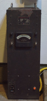
This conditioner consists of a 20 ampere autotransformer coupled by gearing to a reversible 120 volt AC motor. The control electronics for this unit were vacuum tubes (0A2 voltage regulator tube, anyone?). The premise was that a sagging or surging AC line voltage would be detected and the autotransformer (Variac) turned up or down automatically to compensate, supplying the connected loads with a stable 120 volt AC supply. Of course, I disconnected the old vacuum tube controller, and substituted solid-state relays to control the motor direction. These SS relays connected directly to the output of the above-described controller. Additional modifications were made to the Variac to allow it to ramp up from 0 to 128 volts. This translated into a power dissipation of 0 - 1330 watts when the power was supplied to the lower heating element in my water heater. Mechanical limit switches are installed on the Variac so that the motor ceases to run at the end limits of the Variac's rotation. In fact, the "lower" limit switch also turns the unit off at the end of the day.
So, that's what my system was running for several years to divert excess solar power into the water heater. It did work, although not perfectly. Most of the time, I'd have tempered water in the tank so that I could turn on the top element for a short time to make water for bathing or clothes washing. In the summer, the water would be hot most all the time. Sometimes in summer, the entire 50 gallon tank would be full of 160° water, and I'd have to use a secondary dump load because the tank wouldn't heat any further, the thermal cutout had switched off. Those times, I'd simply burn the power in a oil-type space heater, making the already hot garage even more so.
It always galled me some that was I wasn't able to capture all of the solar power, some of it slipped past while the controller was pulsing slowly up, while other times, I was purchasing power from the utility and dumping it into the heater while the controller was slowly tuning down the "dump". It was time for something better.
Original material ©1996-2026 Mr. Sharkey | All rights reserved