
Load Control 6
One of the basic sketches and associated libraries in the Arduino IDE tutorial is LCD (Liquid Crystal Display), which allows information from the processor to be indicated on a readout for the user to view. I've always considered displays to be PFM (Pure Freakin' Magic), so I copped a small display from a derelict satellite receiver at the radio station and decided to play around with that for an evening or two.
Research showed that most small non-proprietary LCD displays use a generic protocol and can be addressed using a pre-determined set of instructions which were contained in the Arduino library. The rest was pretty simple, although it involved connecting what seemed like a lot of wires to a small connector on the back of the display and a fair amount of finger crossing, as I was not able to find an exact pinout of the particular display I was using. Never the less, after jiggling a few loose connections, I had it working.
I found out fairly quickly that it was just as easy to make the display say rude things as it was to use the insipid "Hello World" example that is shown in so many of the tutorials. While this was momentarily amusing, it didn't really make my project any better.
The default example of LCD display use includes indicating a rolling number representing the number of seconds since the processor was rebooted. This showed me that it was not only possible to pass text to the display, but to use variable strings inside the running program to output readable data. But which particular data was useful to me? I tried using the display to show the direction of rotation of the meter disc, or whether it was standing still, but the rapid changes in disc rotation detection made this value difficult to read, it flittered around so quickly so as to be undecipherable. In reality, the read and green LEDs did a better job of telling me what the disc was doing.
For a while, I tried displaying the triac PWM value (0 - 255), but because the system was still running on the Variac, this had little meaning, the triac value wasn't always in sync with the actual state of dumping power into the water heater. Even if the triac had been in use, the value of the PWM driving it wouldn't have a useful meaning, as the power passed through a thyristor isn't linear in relation to the phase angle triggering it.
No, something else needed to be displayed before it was worth integrating a display into this project. Something that had real-world meaning. Something that could be tabulated at the end of the day.
The one useful piece of information I could think of was how many watts of power were being diverted to the water heater. In order to calculate this, I'd need to know how much current was being supplied to the heating element from the Variac. A quick dive into the parts junk box turned up a current sensor that was designed to supply a 0 - 5 volt DC voltage in response to a 0 - 10 ampere AC current passing through it's center. Installing this was easy enough, as I have access to the wiring. A few lines of code in the Adruino sketch and I had it working.
Unfortunately, the readings displayed on the LCD were not encouraging. Back when this system was first installed, I made up a chart and posted it on the wall above the Variac. By reading the analog volt meter on the Stabiline (Variac) front panel, then cross-referencing that number on the chart, I could determine the exact power going into the water heater at any given time.
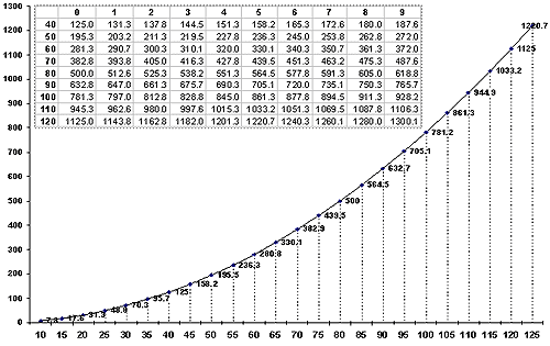
The current and wattage readings on the LCD weren't even close. I used a serial connection to check the string variables running in the program, and checked them against the DC voltage presented at the analog input pin. Everything checked out. Time for more investigation.
What I found was that the current sensor didn't even begin to put out any voltage until the current was close to 1 ampere, and even then the voltage wasn't proportional to the actual current. I set up a test and logged the results, running 1, 2, 3, etc amperes through the current sensor and writing down the results. Although the sensor did indeed put out 5 volts DC at 10 amperes, it didn't put out 2.5 VDC at 5 amperes, or 1.25 VDC at 2.5 amperes. The current-to-voltage relationship wasn't linear, or at least linear enough for my liking.
No, not good enough. Time to try something different...
Original material ©1996-2026 Mr. Sharkey | All rights reserved