
Load Control 7
Very early in my research for this project, I happened upon the Open Energy Monitor project, a group of people who had come together to explore the hardware, software and philosophy of monitoring one's own energy use, including electricity, gas, water and whatever else (wonder if I could put an Arduino to work on my wood stove?). The site included examples of whole-house energy monitoring, rather like an all-inclusive "Kill-a-Watt" meter. The hardware needed to do this was actually very basic, schematics and part descriptions were supplied, as were the Arduino sketches needed to make it all work and return results. There were even users who were using the Arduino to control excess solar production by dumping power into water heaters!
I guess if I had discovered this site before I had invested as much time and energy into the optical mouse project, I probably would have simply built a monitor as described on that site and modified it to do what I needed, there was no reason that the designs there couldn't have done exactly what I was proposing, perhaps more accurately. All of the electric utility metering projects used current transformers (CTs) to sense what the load was on the utility lines. These transformers were clip-on jobs, which meant that no modification to the wiring was necessary. Several different models of CTs were discussed, and resources for purchasing them given. All of the CTs discussed had known specifications that could be plugged into the sketches to make them operate properly.
Since I have a copious "junk box" (a whole building of the stuff, really), I decided to try out a couple of CTs that I had on hand. Here's the two CTs and the AC current sensor that I had tried previously:
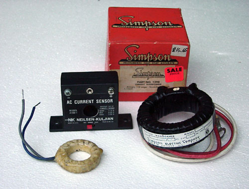
The large Simpson CT was a 150 ampere metering unit, meant to drive a 5 ampere meter movement. I was hoping to not have to use it, as it was so large. The smaller CT on the left was my first choice, but I had no information about it whatsoever, it was a take-off part from my rebuilding of the Lestronic battery charger project.
The first thing to do was to determe the value of the needed "burden resistor". (A note: I'm leaving out a lot of theory in these posts, if the reader is actually interested in learning more, a wealth of information awaits a patient search of the rest of the web, I'm not attempting to come off as the font of all knowledge) Usually, the burden resistor is chosen on the amount of current being measured in conjunction to the turns ratio of the CT. Since I didn't know the turns ratio, but had seen the value of 100Ω used quite a lot, so I decided to start there.
Since linearity was a big issue, I decided to run my current test and measure the resulting voltage across the burden resistor, which is what the Arduino would be doing to determine the operating current in the circuit. Things went pretty well up to a point, then at a certain amount of current, the numbers stopped getting larger as fast as they should. I had obviously hit some kind of "knee" in the CT/burden resistor circuit. Maybe a larger resistance was called for. I increased the burden resistance to 270Ω , which made the descrepancy quite a lot worse. I was going the wrong direction, the resistance needed to be less.
Since adjusting the current and writing down the results, doing mental tabulations along the way was time consuming and not all that much fun, I decided there must be a better way to observe the effects of changing the burden resistor value. Out came the oscilloscope. Since the voltage I was measuring was isolated from the utility line, and the voltages involved were low (below 2 volts), the scope could be connected directly across the burden resistor, and the current then adjusted up until I saw some anomaly in the waveform.
At first, I wasn't sure what I was looking for, clipping of the waveform peaks I assumed. What I found was the opposite, the zero-crossing was getting messed up with the higher resistances. Here's three photos of the scope traces at 10 amperes, showing what I found:
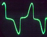
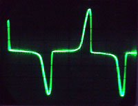
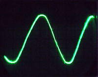
The first photo is with the burden resistor at 100Ω. The waveform had been fine up until about six amps, then distortion started setting in and worsened as the current increased. The second photo is with a 270Ω resistor which started to distort much earlier, and the last is using a 30Ω resistor. Basically, I kept lowering the resistance until I stopped seeing distortion at ten amps, which was my upper limit of measuring. If I had needed this CT to measure more current, it would have required an even lower value of the burden resistor.
Running a complete set of current-vs.-voltage measurements and writing them down showed that the voltage induced across the burden resistor was absolutely linear from 1 to 10 amperes. Exactly what I had hoped for, but I still didn't have what I needed to know to plug these values into the Arduino sketch. Fortunately, the Open Energy Monitor site contains some equations for determining the current in the burden resistor which also allowed me to calculate the turns ratio for the CT that I wanted to use. The end result was that my CT had a ratio of 200:1.
Plugging these values into the "basic energy monitor" Arduino sketch supplied on the site and doing a few code modifications resulted in the current sensing value running inside the program to be exactly correct while using a simulated CT voltage as indicated by my current/voltage graphs. I threw the Adruino running this program on the system (by now the Nano had arrived and it was doing duty on the Variac controller), connected it up to the CT and let it fly. A few calibration tweaks were necessary with the real world current sample voltages, but nothing that a few minutes of editing code didn't correct.
Now that the accurate current values were running inside the program, it was a simple matter to use them and a given constant to calculate power in watts being sent to the dump load. Notice that I have never made reference to measuring or sensing voltage in this system, other than voltage values needed to determine operating values. The Open Energy Monitor programs all use line voltage, either measured or stated to calculate power, but my situation is different, the voltage on the heater element varies from 0 - 129 volts. Since the load on the system is constant and given - a water heater element - I was able to measure the ohmic value of that element and use that in my calculation of power. Basically, ohms Law states that power (P) equals Current (I) squared times Resistance (R), or P=I²R. In the Arduino sketch, this is expressed as:
watts = (Irms * Irms) * 12.3; // 12.3 = load resistance in ohms
The next (and final) item on the clipboard was that now that I could read watts, I could also accumulate watthours for display. A post over at the openenergymonitor.com site brought a response from a seasoned user, and I inserted some additional code to keep a running total of the watthours, to be reset at the end of each day.
Bringing it all together, the current measurement, the wattage calculation, the watthour total and my new knowledge of LCD PFM resulted in a display that suited my expectations:
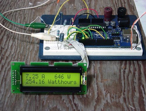
The display is showing current, wattage into the water heater load, and total dump load consumption for the day, which isn't much in this photo, as I took the image fairly early in the morning.
Yes, I'm still working on a partial sheet of plywood perched on top of the clothes dryer. All that's left to do now is actually build this project. That's never the most fun part for me, but there's a fairly large amount of satisfaction once it's done.
Oh, and to finish up, here's some code to keep you interested until I have some actual construction photos to share. Sorry for the brevity of some of the code and comments, I tend to be a bit of a minimalist when it comes to writing this stuff:
#include <LiquidCrystal.h>

// initialize the library with the numbers of the interface pins
LiquidCrystal lcd(12, 11, 5, 4, 3, 2);

const int resetPin =  6;      // the number of the Wh reset pin

//Setup variables
int  inPinI = 1, numberOfSamples = 3000, lastSampleI, sampleI, resetState = 0;
double watts = 0.0, whTotal = 0.0;  //watts up?
double I_RATIO = 0.0354;  //calibration variable
double lastFilteredI, filteredI, sqI, sumI, Irms;      // current things
unsigned long ltmillis, tmillis, timems, startmillis;  //time stuff

void setup()
{
  lcd.begin(16, 2);  // set up the LCD's number of columns and rows:
  //  Serial.begin(9600);
  tmillis = millis();
  startmillis=tmillis;
  pinMode(resetPin, INPUT); // reset Wh display
}

void loop()
{

  for (int n=0; n<numberOfSamples; n++)
  {

    //Used for offset removal
    lastSampleI = sampleI;

    //Read in current samples.
    sampleI = analogRead(inPinI);

    //Used for offset removal
    lastFilteredI = filteredI;

    //Digital high pass filters to remove 2.5V DC offset.
    filteredI = 0.996*(lastFilteredI+sampleI-lastSampleI);

    //Root-mean-square method current
    //1) square current values
    sqI = filteredI * filteredI;
    //2) sum
    sumI += sqI;
  }

  //Calculation of the root of the mean of the voltage and current squared (rms)
  Irms = I_RATIO*sqrt(sumI / numberOfSamples);
  watts = (Irms * Irms) * 12.3;  // 12.3 = load resistance in ohms

  //Calculate amount of time since last realpower measurment.
  ltmillis = tmillis;
  tmillis = millis();
  timems = tmillis - ltmillis;

  //Calculate todays number of kwh consumed.
  whTotal = whTotal + (watts * 1.0/3600.0 * (timems/1000.0));

  // reset Wh display?
  resetState = digitalRead(resetPin);
  if (resetState == HIGH) {
    whTotal = 0.0;
  }

  /*
  //Output to serial
   Serial.print("Amps=");
   Serial.print(Irms);
   Serial.print("   Watts=");
   Serial.println(watts);
   */

  lcd.setCursor(0, 0);
  lcd.print(Irms, 1);
  lcd.print(" A   ");

  if (watts >= 1) {
    lcd.setCursor(9, 0);
    lcd.print(watts, 0);
    lcd.print(" W    ");
  }
  else {
    lcd.setCursor(7, 0);
    lcd.print("<1 Watt");
  }

  lcd.setCursor(0, 1);
  lcd.print(whTotal, 1);
  lcd.print(" Watthours   ");

  //Reset accumulator
  sumI = 0;
}
Original material ©1996-2026 Mr. Sharkey | All rights reserved