
Load Control 8
Although I thought I was close to actually constructing this project, it turns out that I've stuck myself into more development before getting that far.
Early in the experimentation around the Watthour calculator, I realized that I would need a second processor. Since the current sensing code in the Watthour calculator samples the current 3,000 times before using mathematical calculations to average out the current, the circuit runs a bit on the slow side. This isn't a problem for the display, but I could foresee problems if the controller itself had so much delay when it should be busy adjusting the Variac. I tried lowering the number of samples, but this quickly resulted in jittery and inaccurate readings and calculations.
For the price of a second Nano, I wouldn't have to be concerned how many clock cycles the display used up, so I ordered a second one from the auction site.
While waiting for that processor board to arrive, I discovered an excellent site that offered quite good tutorials on Adruino. Getting Started with Arduino presently has 44 chapters on a variety of useful small projects designed to teach the basics of microprocessor development. I know that I really learned a lot, even though I kind of glossed-over the deeper technical aspects of some of the stuff I wan't sure I had an immediate use for.
One of the tutorials had a quick description of using an Amtel ATMega328 chip without an Arduino board. I had seen some references to this elsewhere, but no real examples were given. Since I was assembling an order of parts for the meter construction, I included a couple of the chips and the 16 MHz ceramic resonators needed to make them run. The end result is supposed to be that the 28 pin chips can do any and everything that a full Arduino board can do (with a few small limitations), and the ATMega328 is even smaller by itself than the Nano board.
One of the construction aspects that I hadn't worked out yet was what I was going to do about the couple of external switches I needed for mouse sensitivity and Watthour total reset. I had thought I'd use a polycarbonate dome that could be drilled for switches, but none of those I have will fit the old, analog meter base that I'll be building on. This means that I'll need to fit the heavy glass dome on the base when I'm finished, effectively sealing myself out of the environment. I assumed that I'd have to run some wiring out the back of the meter and build a small switch panel next to the meter base.
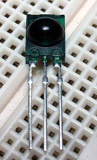
Continuing to read the Arduino tutorials, I came upon chapter 32, Infra-red control. This clever bit described how to use a common TV or DVD remote control and a tiny, $1 sensor to get control signals into an Arduino sketch! It didn't take long for me to recognize that this was the way to get through that glass dome!
I had already sent in my parts order, and didn't want to make another so soon for a single part, so I began thinking about what I might have on hand that I could cannibalize for this sensor. The answer was as close as my storage shed, an old Sharp DVD player that worked fine, except it would frequently "stick" at 23 minutes into any interesting movie that it decided I shouldn't see. A couple of minutes with a screwdriver and a soldering iron got me the component I needed to begin experimenting:
The Arduino library for reading the sensor was available, so I set up a simple sketch to read the output of the Sharp remote control. Well, it didn't work, every button I pressed returned a "0" (zero) on the serial monitor. More research provided the fact that Sharp uses a non-standard protocol for encoding the IR data. There were some code examples that I could plug into the Arduino IR library to possibly fix this issue, but I really didn't want to mess with it. Instead, I grabbed the remotes from my new DVD, VCR, and an old Radio Shack "universal" remote. These did return data codes that I could decipher, and the Radio Shack remote had the additional bonuses of being small, programmable for a variety of code regimes, and not currently needed to control any of my home entertainment equipment.
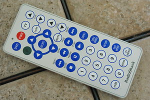
Not every button on the control is active, and some return duplicate codes when pressed, but there were enough useful buttons that I thought I could do something with it.
Integrating the IR library into the controller sketch wasn't difficult, and after changing the code a bit, I was easily able to control the sensitivity (high/low) of the mouse by pressing the volume up/down buttons on the remote. Once that was working, my mind starting wrapping around exactly what this meant, I could control the behavior of the program while it was running by pressing buttons from across the room! I immediately started thinking up other functions for the remaining buttons on the remote:
- (Play button), Set the controller to adjust the Variac level according to the data returned by the optical mouse.
- (Pause button), Make the controller ignore the mouse, but allow me to adjust the Variac using the Channel up/down buttons.
- (Stop button), "Park", Ignore all outside inputs and send the Variac to "full off" position (useful for shutting down the system for maintenance)
The one remaining function I wanted was to be able to reset the Watthour total on the display, but because that data was on the other microprocessor board, I was going to have to send a signal from the controller board to the display board. I assumed that I'd use a free pin on the Arduino and use digitalWrite() to send a voltage to the other board and decode it with a spare pin on that end. Then I remembered that these processors have a built-in serial UART port. Could these be made to communicate between the two processors?
A quick search brought up a library called EasyTransfer which allowed a simple one-way, or two-way transfer of data between Arduino boards. I set up a simple test, and it worked as described, a variable string from one board could be transferred to the other, where it could be used to alter the programming on that board.
I still had a lot of buttons left on the remote, but other than the reset I wanted, I couldn't think of much to do with the additional abilities that the serial connection afforded. For a while, that is, then I started rolling out ideas, eventually adding five more screens to the display, each controlled by the numeric buttons on the remote:
- (#1 button), main display, Amps, Watts, and Watthours
- (#2 button), A status display, Mode auto/manual/parked, and Sensitivity high/low.
- (#3 button), Since it's not possible to tell what sketch is loaded on a processor, I include a variable string with the version number in each update of the sketch which displays in this mode, Controller v2.55, Display v2.31 as of this writing. This makes it much easier to know what is actually running in the program.
- (#4 button), A display of the days, hours, minutes, and seconds that the processor has been running.
- (#5 button), Contrast. Since the LCD display needs a voltage between 0-5 volts to set the contrast of the display, I needed a way to set this. The "easy" way is usually to use a potentiometer on the circuit board, but that means having an adjustment under the glass dome, so I wrote a variable into the program to use one of the pins on the display board to set the voltage using PWM, adjusted with a context-sensitive use of the volume up/down buttons. These change the digital value of the contrast variable from 0-255, and output the result using analogWrite(). The volume buttons only control the value of this variable when the display is in mode 5, other times, the volume buttons control the sensitivity of the mouse.
- (#6 button), Reset Watthour Total. I found that once in a while, the serial connection would miss a beat, and when it did, the display would blank out for an instant, and at the same time, the Watthour total would reset to 0.0. This was abhorrent behavior, and not acceptable. I could deal with the display going blank for 5 seconds every few hours, but resetting the Wh was not OK. I wrote a switch into the program that allows resetting the Wh only from display mode 6 when the "DSPLY" button on the remote was pressed. Since the display normally sits in mode 1, main display, any glitches in the data shouldn't emulate the combination of conditions necessary to reset the Wh total.
At this point, that's it. Unless I can think of any more button functions I can include, or I suddenly decide to put in a shoe-shine library or teach the dual Arduino processors to roll and smoke cigarettes, I'm ready to get the construction under way. Oh, well, I guess there is that little matter of teaching myself how to install a bootloader on those raw ATMega328 chips I bought, but that should be easy.
(update, Oct, 2012) More as the project progresses, I'll be putting some time into it over the winter...
Original material ©1996-2026 Mr. Sharkey | All rights reserved